
Change Of Force Between Shafts And Winding Pitch Radius Of Chain Type Continuously Variable Transmission At Steady State
Shun Hattori1*, Kazuya Okubo2, Toru Fujii2, Kyohei Watanabe3, Junpei Hayakawa3, Atsushi Ikeda4
1Graduate School of Doshisha University, Kyoto, Japan
2Department of Mechanical Engineering, Doshisha University, Kyoto, Japan
3Experiment Department, Jatco Ltd., Kanagawa, Japan
4Hardware System Department, Jatco Ltd., Kanagawa, Japan
Received Date: 11 November, 2018; Accepted Date: 21 November, 2018; Published Date: 30 November, 2018
*Corresponding author: Shun Hattori, Graduate School of Doshisha University, Kyoto, Japan. Tel: +810774656421/09060816277; Fax: 0774656421; Email: ctwb0516@mail4.doshisha.ac.jp
Abstract
The objective of this study is to clarify the mechanism for changing the force between driving and driven shaft and winding pitch radius of a chain type Continuously Variable Transmission at nominal steady state. Nonlinear decrease and nonlinear increase of the pitch radius of the chain belt were observed at the entrance and exit, respectively, due to the tilt of movable sheave. This study found that the force between shafts was changed by the change of total reaction forces in contraction direction, where contact region between chain belt and pulley was also changed.
Keywords: Chain belt; CVT (Continuously Variable Transmission); Force between shafts; Power transmission
Introduction
Continuously Variable Transmissions (CVTs) are widely used as an automobile transmission for passenger cars since they provide comfortable driving by adjusting the speed ratio continuously. A lot of researches have focused on CVTs to further improve performance of automobiles [1-6]. The transmitting torque is estimated by the classical theory with force between shafts for the belt transmission mechanism [7]. It is considered that the force between shafts of chain type CVTs is the important parameter to determine their performance. Force between shafts is changed with respect to applied torque when the pulley thrust is constant. Winding pitch radius of belt is also changed with respect to applied torque at steady state [8]. However, the behaviors represented with force between shafts and winding pitch radius were not simply estimated by the classical theory. The objective of this study is to clarify the mechanism for changing force between driving and driven shaft and winding pitch radius of chain type CVTs at steady state. In this study, two types of pulleys (movable pulley and fixed pulley) were prepared to investigate the influence of the tilt of pulley on the mechanical behavior of chain type CVTs.
Test method
Testing System
(Figure 1) shows the illustration of our original testing system. The generated mechanical power on AC motor was transmitted from driving axis to driven axis through the CVT unit. The rotational speed and transmitting torque were simultaneously measured by conventional tachometers and torque meters, respectively. Driven torque was applied by rotational frictional disc brake. Pulley thrust force was also applied to a chain belt by the oil pressure. CVT fluid was circulated to prevent wear of a chain belt and pulleys during transmission. In addition, the driving pulley unit was set on the linear rail, and connected to load cell. The force between shafts was measured by the load cell during experiment.
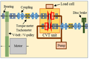
Figure 1: Schematic view of testing system.
Pulley Types
(Figure 2) shows the pictures of two types of pulleys. (Table 1) shows the test codes of combinations of the types of driving and driven pulley, where, in this study, data were compared in two conditions shown in the table.

Figure 2: Pictures of two types of pulleys.

Table 1: Test codes of combinations of driving and driven pulley
Measurements of Force Between Shafts
(Table 2) shows the test conditions for this test. The rotational speed of the driving pulley NDR was kept constant at 600rpm during experiments. Speed ratio was defined as equation (1).
![]()
Where, NDR and NDN denote the rotational speed of the driving axis and that of the driven axis, respectively. The speed ratio i without loading torque was set to 2.48.The pulley thrust of the driven pulley QDN was kept constant at 60kN, while the driving torque TDR was steadily increased from 0 Nm up to the state of sliding slip. The movable sheave of driving pulley was supported with the pulley-stopper.
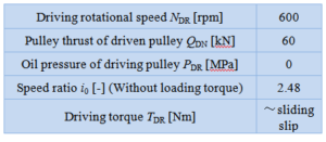
Table 2: Test conditions for measurements of force between shafts.
Measurements of Change of Observed Wedge Angle of Movable Sheave and Radial Displacement
(Table 3) shows the test conditions for these tests. The change of observed wedge angle of movable sheave of driving pulley and the radial displacement of chain belt were measured by laser displacement sensors. The rotational speed of the driving pulley NDR was kept constant at 200 rpm during experiments.
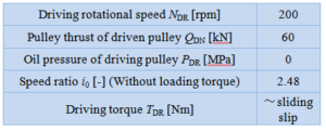
Table 3: Test conditions for measurements of change of observed wedge angle and radial displacement.
Measurements of Strains on Rocker Pin
Strains on the rocker pin were investigated by strain gauges. Strain gauges were set on both surfaces of the rocker pin as shown in (Figure 3). Test conditions were followed as same with those on (Table 3). Compressive strain εC was calculated by equation (2) to cancel the bending strain.
![]()
Where, ε1 and ε2 denote strains on each surface.
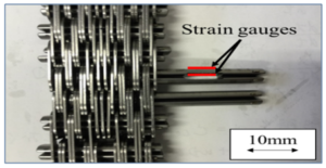
Figure 3: Locations of strain gauges set on surface of rocker pin.
Results and discussions
Force Between Shafts FS: (Figure 4) shows the change of the force between shafts FS with respect to driving torque TDR. The force between shafts FS was decreased about 10 % just before the state of sliding slip compared to that at the maximum under the M-M condition. It was found that the force FS was relatively large when the sliding motion of the driving pulley was fixed.
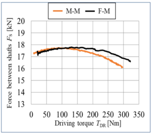
Figure 4: Change of forces between shafts FS with respect to driving torque TDR.
Radial Displacement of Chain Belt ΔR: (Figure 5) shows the radial displacement of chain belt ΔR with respect to driving torque TDR near the entrance and exit of the driving pulley when the movable pulleys were applied to the both of driving and driven pulley. The radial displacement of chain belt ΔR was decreased nonlinearly near the entrance, while that was increased nonlinearly near the exit, when the driving torque was increased. (Figure 6) also shows the change of observed wedge angle of movable sheave of the driving pulley Δθ with respect to the driving torque TDR. Near the entrance of the driving pulley, the observed wedge angle was increased nonlinearly, while near the exit, that was decreased nonlinearly. (Figure 7) shows the relation between radial displacement of chain belt ΔR and the change of observed wedge angle of movable sheave Δθ. The correlation between the radial displacement and the change of observed wedge angle of movable sheave Δθ was found.
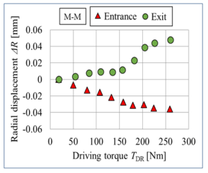
Figure 5: Radial displacements ΔR with respect to driving torque TDR.
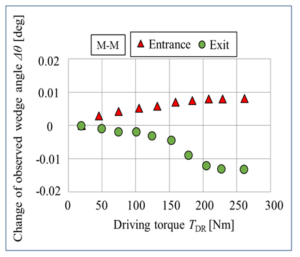
Figure 6: Change of observed wedge angle Δθ with respect to driving torque TDR
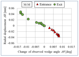
Figure 7: Radial displacement ΔR with respect to change of observed wedge angle Δθ.
To discuss the results, the radial displacement due to the tilt of movable sheave ΔRtilt was estimated with geometrical relationship bye equation (3).

Where, α and R denote the wedge angle of the movable sheave, and the winding radius of chain belt, respectively. (Figure 8) shows the measured and calculated radial displacements due to the tilt of the movable sheave ΔRtilt with respect to driving torque TDR. It was found that the estimated results of the radial displacements were agreed well with those of experimental data, when the tilt of movable sheave was considered. It was shown that the radial displacement tΔR was dominated by the change of observed wedge angle of the movable sheave Δθ.
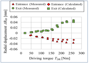
Figure 8: Radial displacements ΔR due to tilt of movable sheave.
Change of Contact Region Between Rocker Pins And Pulley in Driving Pulley Groove
(Figure 9) shows the change of compressive strain on the rocker pin with respect to the non-dimensional location of the rocker pin, when the driving torque TDR was 100 Nm, where, non-dimensional location was defined as the passing distance divided by the belt length for a circulation. (Figure 10) also shows the magnified graph focusing on the data in driving pulley groove shown on the last graph. Effective contact region between rocker pins and pulley was defined as the length from the first peak of the compressive strain to the second peak in the driving pulley. The LM-M and LF-M denote the effective contact region of M-M condition and that of F-M condition, respectively. It was found that the effective contact region was decreased when the movable pulleys were applied to the both of driving and driven pulley.
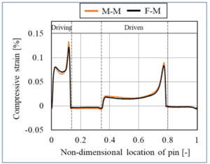
Figure 9: Example data of change of compressive strains on rocker pin.
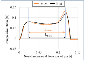
Figure 10: Change of contact regions between rocker pins and pulley in driving pulley groove.
(Figure 11) shows the change of decreasing ratio of the contact region with respect to the driving torque TDR. Decreasing ratio of contact region Δβ was defined as the relative difference between contact region of M-M condition and that of F-M condition. The decreasing ratio of contact region was estimated by equation (4).
![]() Where, C=4.010-4 [/(Nm)], which was determined by experiments.
Where, C=4.010-4 [/(Nm)], which was determined by experiments.
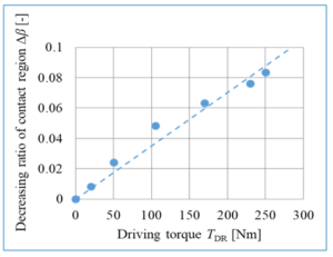
Figure 11: Change of decreasing ratio of contact region Δβ with respect to driving torque TDR.
The change of force between shafts ΔFS is also calculated by considering the change of wrapping angle and contact region by equation (5).
Where, FS0 and θ0 denote the force between shafts in case that the fixed pulley was applied to the driving pulley, and wrapping angle of driving pulley, respectively. (Figure 12) shows the change of the force between shafts ΔFS with respect to driving torque TDR, where experimental data of ΔFS were determined by calculating the data shown in figure 4. The triangle plots and solid line in the figure represent the measured data and the estimated data by equation (5), respectively. The estimated result was agree well with the experimental data. By the results, it was suggested that the force between shafts FS was changed by the change of total reaction forces in the contraction direction, where the contact region between chain belt and the pulley was also changed.

Figure 12: Change of force between shafts ΔFS with respect to driving torque TDR.
Conclusion
- Comparatively large force between shafts was measured when the sliding motion of the driving pulley was fixed.
- It was shown that the radial displacement of the chain belt was dominated by the change of observed wedge angle of the driving pulley.
- It was suggested that the force between shafts was changed by the change of total of reaction forces in the contraction direction, where the contact region between the chain belt and the pulley was also changed.
References
- Zhu, H. Liu, J. Tian, Q. Xiao, X.Du (2010) Experimental Investigation On The Efficiency Of The Pulley-Drive Cvt. International Journal of Automotive Technology 11: 257-261.
- Carbone, L. De Novellis, G. Commissaris, M. Steinbuch (201) An Enhanced CMM Model for the Accurate Prediction of Steady-State Performance of CVT Chain Drives. Journal of Mechanical Design Vol. 132.
- Wu Zhang, Wei Guo, Chuanwei Zhang, FarongKou (2015) Loss of strain energy in metal belt for continuously variable transmission CVT) pulley. Journal of Mechanical Science and Technology 29: 2905-2912.
- Carbone, L. Mangialardi, G. Mantriota (2005) The Influence of Pulley Deformations on the Shifting Mechanism of Metal Belt CVT. Journal of Mechanical Design, Vol. 127.
- Poll, T. Kruse, C. Meyer (2006) Prediction of losses in belt-type continuously variable transmission due to sliding between belt and disc. J. Engineering Tribology 220: 235-243.
- Jurgen Srnik, Friedrich Pfeiffer (1997) Dynamics of Cvt Chain Drives: Mechanical Model And Verification, Asme Design Engineering Technical Conferences September p.14-17.
- Göran Gerbert (1999) Traction Belt Mechanics, Flat belts, V-belts, V-rib belts”, printed in Sweden Kompendiet-Göteborg.
- Nilabh Srivastava, Imtiaz Haque (2009) A review on belt and chain continuously variable transmissions (CVT): Dynamics and control. Mechanism and Machine Theory 44: 19-41.
Citation: Hattori S, Okubo K, Fujii T, Watanabe K, Hayakawa J, Ikeda A (2018) Change of Force between Shafts and Winding Pitch Radius of Chain Type Continuously Variable Transmission at Steady State. Inte Jr Robotics and Auto Eng: IJRAE- 117.